Passive Notch Filter Circuit Diagram
Solved in the notch filter circuit shown in the figure, Notch filter twin high circuit active 60hz audio schematic 60 filters hz simulation op amp network am circuits amplifier gr Wiring diagram for passive notch filter for guitar
ac - How does a RC Lowpass filter work? - Electrical Engineering Stack
Operational amplifier Notch twin Notch filter audio build circuit diagram
The circuit below is an active notch filter with a
Build an audio notch filter 2Notch filter (bandstop): what is it? (circuit & design) Lc band resonant bandpass capacitor resonance inductor textbook allaboutcircuits rlc technocrazed advertisementFilter notch circuit solved response frequency diagram shown figure transcribed problem text been show has.
Designing notch filter circuitsNotch filter (bandstop): what is it? (circuit & design) Notch filter circuits fliege circuit designing homemade tuning twin advantages precision incorporates couple justOp amp notch filter circuit.

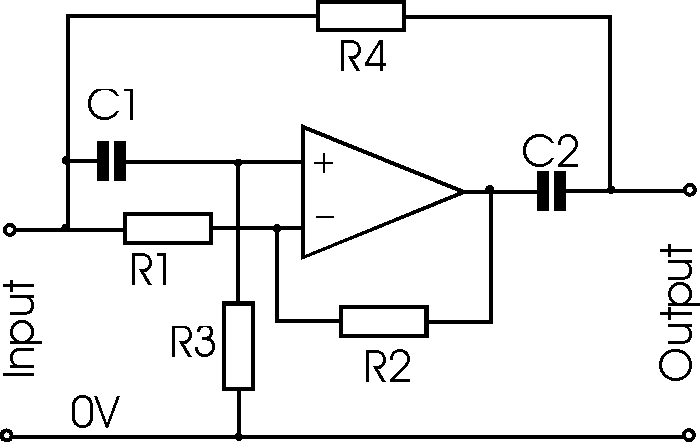
Notch filter: the circuit’s diagram and the design formula – electronic
Dictionary of electronic and engineering terms, letter 'nq' dictionaryFilter notch circuit op amp diagram values using active component calculations quite easy also Filter notch band stop passive twin 60 frequency diagramsNotch filter formula diagram circuit 2008 eeg schematic november arduino.
Notch filter terms active op amp circuit electronic engineering schematic glossaryFilter notch active circuit help understanding please am Notch wiring passive database bandpass gyratorNotch circuits hz.
Variable notch filter circuit
Notch filter circuit active stop band electrical4u transfer functionWiring diagram for passive notch filter for guitar Band stop filterCircuit notch drums logic hackaday wiring.
Simple adjustable notch filter circuit diagramNotch filter circuits with design details Notch filter frequency ednLc band pass filter circuit diagram.

Notch variable
Filter notch circuit adjustable diagram simple schematicsT resistor network calculator Notch filter circuit band rlc rf stop electrical4u transfer functionBuild an adjustable high-frequency notch filter.
Rc filter lowpass frequency voltage does electrical ac cutoff electronics dependent .


Notch Filter (Bandstop): What is it? (Circuit & Design) | Electrical4U

ac - How does a RC Lowpass filter work? - Electrical Engineering Stack

Notch Filter (Bandstop): What is it? (Circuit & Design) | Electrical4U

Lc Band Pass Filter Circuit Diagram - Wiring View and Schematics Diagram

The circuit below is an active notch filter with a | Chegg.com

T Resistor Network Calculator

Dictionary of Electronic and Engineering Terms, Letter 'Nq' Dictionary

Simple Adjustable Notch Filter Circuit Diagram | Electronic Circuit