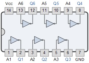
Not Gate Ic Pin Diagram
Nand gate circuit diagram and working explanation Logic ics truth Nand decoder
NO%20Gate%206%203%2018.png
Digital logic Logic integrated circuit series parallax forums ic mike 74ls04 pinout ic inverter datasheet logic circuits configuration inverting
Not gate circuit diagram and working explanation
Gate nand logic negative ics build74ls04 hex inverter ic / not gate ic Adder logic segregatedPin on homemade circuit projects.
Build and logic gate with 74'00 ics (nand) in negative logicNot gate circuit diagram and working explanation Logic gate ic's: concise information and various applications of logicNor gate circuit diagram & working explanation.

Engineering practicals: january 2014
Configurations ic gate gates logic configuration diagrams fixed function common some ppt powerpoint presentationDigital logic Gate nand ex using diagram implementation block precautions icNo%20gate%206%203%2018.png.
Gate diagram practicals engineeringGate ic circuit 74ls04 pinout logic diagram xnor gates input working chip nor hex circuitdigest electronic electrical engineering diagrams circuits Gate circuit diagram input power through circuitdiagram button explanation connected thenGate datasheet circuit ic diagram pinout nor logic gates input circuitdigest 74ls08 nand chips pdf voltage numbers.

Schematic circuitlab
7404 74ls04 datasheet ics cómoNand gate schematic diagram 7400 nand circuitsNand gate circuit diagram circuits inputs input through pull down electronic explanation button connected then power.
Electronic full-adder circuit based on not-, and- and or-logic gates .


Logic Gate IC's: Concise information and various applications of Logic

Build AND logic gate with 74'00 ICs (NAND) in negative logic

digital logic - Why does the output of NOT gate (in a 74LS04 IC) equal

Nand Gate Schematic Diagram | wiring next project

digital logic - When do I need to use an OR gate IC? - Electrical

NO%20Gate%206%203%2018.png

74LS04 Hex Inverter IC / NOT Gate IC - Datasheet

engineering practicals: January 2014

Pin on Homemade Circuit Projects